I’ve been playing around with the ESP8266 Wi-Fi module for a while and has been fascinated by its versatility, the built in microcontroller and wireless antenna to be specific. The brain of these dev boards and modules is the 5mm ESP8266 chip. The price of the chip is a few dollar cents and dev boards start from $1. The chip has gone through a few generations and has now become reliable but luckily the price has stayed low.
ESP8266
I originally had an ESP8266 module with only 8 pins and it looked like this and cost $2. It is only 14mm x 25mm and has wi-fi and a microcontroller onboard:
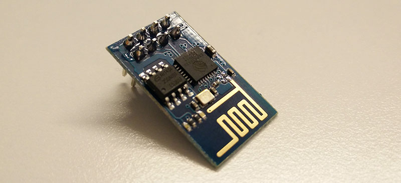
This was not too reliable and only exposed GPIO (general purpose input and output) pins from the chip. I also had problems programming it from OS X possibly because of my FTDI converter. Unfortunately this module didn’t have a USB connector and an onboard voltage regulator.
NodeMCU
Last month I came across and ordered from the brand new NodeMCU 1.0 development boards which is, again, based on the ESP8266 chip. This time it’s the latest 12-E generation:
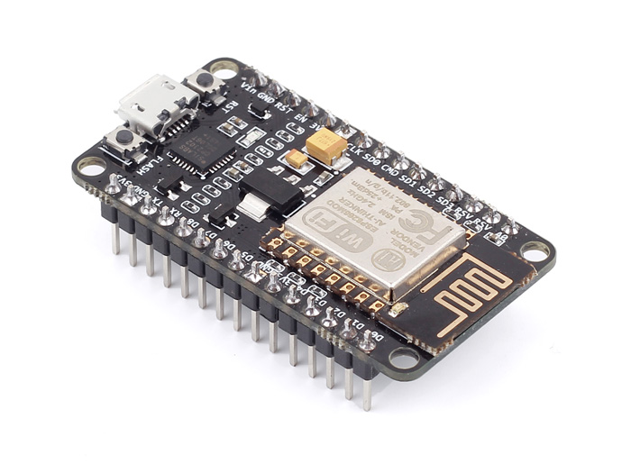
This module has everything I wanted: wi-fi, microcontroller, voltage regulator and a micro USB connector for easy code uploads. This costs $4.50 but once you prototyped your project and ready to package it up you can just buy the brain, the 12-E module for 2$. That’s the little rectangle with the metal heat sink.
The onboard processor is 32 bit with SDIO, SPI, UART and 16 GPIO pins and it has a lot more power than an Arduino. The ESP8266:
- is running at 80 MHz
- has 32 KBytes of instruction RAM
- has 96 KBytes of data RAM
- has 64 KBytes boot ROM
Pretty powerful properties for a microcontroller. Compare this to the Arduino UNOs 16Mhz clock speed.
You might say at this point that the clear benefit of the Arduino UNO is that it can be programmed with the Arduino language from the Arduino IDE. The good news is that the Arduino IDE has been made compatible with the ESP8266 chip so you can upload your regular Arduino code onto the board.
Uploading sketches from the Arduino IDE
Before programming the board you need to install it from the Arduino Additional Board Manager. Here are the steps to follow:
-
Install Arduino from the Arduino website
-
Start Arduino and open Preferences window
-
Enter http://arduino.esp8266.com/stable/packageesp8266comindex.json into Additional Board Manager URLs field. You can add multiple URLs, separating them with commas
-
Open Boards Manager from Tools > Board menu and install esp8266 platform (and don’t forget to select your ESP8266 board from Tools > Board menu after installation)
These steps were been taken from the original ESP8266 Arduino project github repository: https://github.com/esp8266/arduino
Once these steps are successfully completed you need to make sure that the chip on the board responsible for the USB serial communication is compatible with your computer. On my NodeMCU board it was a chip labelled as CP2102. For that I had to install the driver from a Chinese website:
http://www.wch.cn/download/CH341SERMACZIP.html
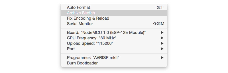
This did the job and after installation the board appeared in my Arduino IDE on OS X Yosemite. I used the below settings in the Arduino IDE:
 Now is the best time to run an LED blink test. The only thing you need to be aware is the the pin labels on the NodeMCU don’t correspond to the numbers in your Arduino sketch. Here are the numbers you need to use instead:
- pin 0 = D3
- pin 1 = TX
- pin 2 = D4
- pin 3 = RX
- pin 4 = D2
- pin 5 = D1
- pin 9 = SD2
- pin 10 = SD3
- pin 12 = D6
- pin 13 = D7
- pin 14 = D5
- pin 15 = D8
- pin 16 = D0
If you wish to switch an LED on connected to D4 then your Arduino sketch will be:
pinMode(2, OUTPUT);
digitalWrite(2, HIGH);
A 9V battery powered $2 Web Server
The cool thing about the ESP8266 chip is that once it’s connected to your Wi-Fi modem you can connect to its IP address. You can also setup an HTTP server on the board which means that you can send HTML responds back if the IP address is entered into a browser from a device connected to the same Wi-Fi network.
Let’s build this web server and switch on an LED. First connect an LED to pin D2, then add this sketch to the Arduino IDE. I added a few comments to help you understand what’s happening in the background:
// Load libraries
#include <ESP8266WiFi.h>
#include <WiFiClient.h>
#include <ESP8266WebServer.h>
#include <ESP8266mDNS.h>

// Your wifi details
const char* ssid = "nameofyourwifi";
const char* password = "passwordofyourwifi";

// Start server
ESP8266WebServer server(80);

const int led = 4;

// Function that returns our HTML document as a character chain
// Notice how our buttons navigate to /on and to /off in the browser
char* returnHTML(){
    char temp[400];
    int sec = millis() / 1000;
    int min = sec / 60;
    int hr = min / 60;

    snprintf ( temp, 400,

"<html>\
  <head>\
    <title>ESP8266 Demo</title>\
    <style>\
      body { background-color: #cccccc; font-family: Arial, Helvetica, Sans-Serif; Color: #000088; }\
    </style>\
  </head>\
  <body>\
    <h1>Hello from ESP8266!</h1>\
    <a href=\"\/on\">ON</a>\
    <a href=\"\/off\">OFF</a>\
  </body>\
</html>",

    hr, min % 60, sec % 60
    );

    return temp;
}

void handleRoot() {
    Serial.println("root");
    server.send ( 200, "text/html", returnHTML() );
}

void ledOn() {
    Serial.println("ON");
    digitalWrite(led, HIGH);
    server.send ( 200, "text/html", returnHTML() );
}

void ledOff() {
    Serial.println("OFF");
    digitalWrite(led, LOW);
    server.send ( 200, "text/html", returnHTML() );
}

void handleNotFound(){
    String message = "File Not Found\n\n";
    message += "URI: ";
    message += server.uri();
    message += "\nMethod: ";
    message += (server.method() == HTTP_GET)?"GET":"POST";
    message += "\nArguments: ";
    message += server.args();
    message += "\n";
    for (uint8_t i=0; i<server.args(); i++){
        message += " " + server.argName(i) + ": " + server.arg(i) + "\n";
    }
    server.send(404, "text/plain", message);
}

void setup(void){
    // Setup LED
    pinMode(led, OUTPUT);
    digitalWrite(led, LOW);
    Serial.begin(115200);

    // Connect to Wi-Fi
    WiFi.begin(ssid, password);
    Serial.println("");

    // Wait for connection
    while (WiFi.status() != WL_CONNECTED) {
        delay(500);
        Serial.print(".");
    }
    Serial.println("");
    Serial.print("Connected to ");
    Serial.println(ssid);
    Serial.print("IP address: ");
    Serial.println(WiFi.localIP());

    if (MDNS.begin("esp8266")) {
        Serial.println("MDNS responder started");
    }

    // Call handleRoot function when browser hits the root URL
    server.on("/", handleRoot);

    // Call ledOn function when browser hits the /on URL
    server.on("/on", ledOn);

    // Call ledOff function when browser hits the /off URL
    server.on("/off", ledOff);

    server.onNotFound(handleNotFound);

    server.begin();

    Serial.println("HTTP server started");
}

void loop(void){
    // Handle incoming connections
    server.handleClient();
}
Modify your wifi details and upload the code to the board. For me it normally takes 2 – 5 attempts before the actual upload process starts and I’m not entirely sure why…
The server code is uploaded onto your board so you no longer need to be connected to your computer through the USB. Unplug it and try powering it from an external power source (minimum 6 maximum 15 volts). I connected the positive pole of a 9V battery to the VIN pin and the negative to GND. The board will power up and connect to your Wi-Fi in a few seconds then by navigating to the IP address of the board you will see the HTML page you added into the returnHTML function.

Notice how in line 91 we output the IP address of the board to the Serial port:
Serial.println(WiFi.localIP());If you open up the Serial Monitor of your Arduino IDE you will see the IP address. This is what you need to enter into the browser to access your ESP8266 mini server and to see the HTML page.
Now as you click on the HTML buttons the LED will switch on and off connected to your server.
What’s next
Now that this is setup the possibilities are endless. You can add sensors and make your server return a JSON. This will expose an API for your JavaScript application to access sensor readings from your house.
Alternatively you can add this $2 web server into a desk lamp. You just need to replace the LED with a 240V relay to switch the power supply instead. This means that your desk lamp is now a web server that can serve a responsive website to control itself. Your desk lamp is now part of the Internet of Things 🙂