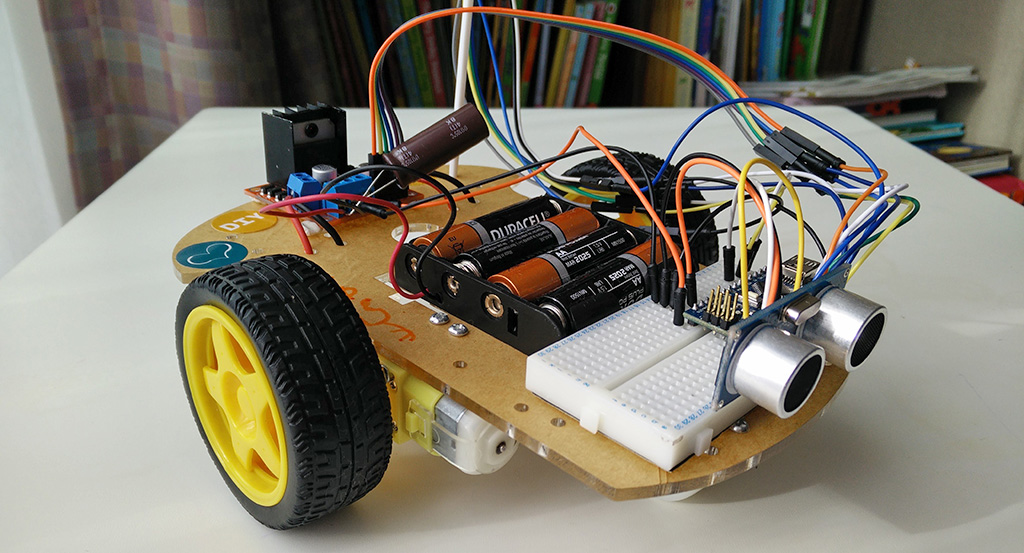
Arduino Robot Car with Obstacle Avoidance. I’ve always been excited about autonomous cars and radio controlled toy cars so it was time for me to build my own with an Arduino Nano. The finished car has two modes. First is manual mode which allows you to drive it wirelessly from an Arduino UNO and a joystick shield. Second is the autonomous mode which drives the car continuously forward and avoids obstacles by stopping and steering away immediately. Obstacles are detected by the ultrasonic sensor attached to the front of the car.
The source code for the project can be found on Github: Car Obstacle Avoidance
Let’s now see how I built this car.
I didn’t want to spend too much time building the chassis so I decided to buy a robot car kit from ebay. After assembling the kit I soldered the wires onto the motors and screwed the 4xAA battery holder then I was ready to add the Arduino electronics.
Motor drive circuit
Driving the motors from the Arduino is not possible as they draw too much current so you need a separate motor drive unit to help the Arduino. I purchased a pretty, red L298N module from ebay. Here’s how it looks like:
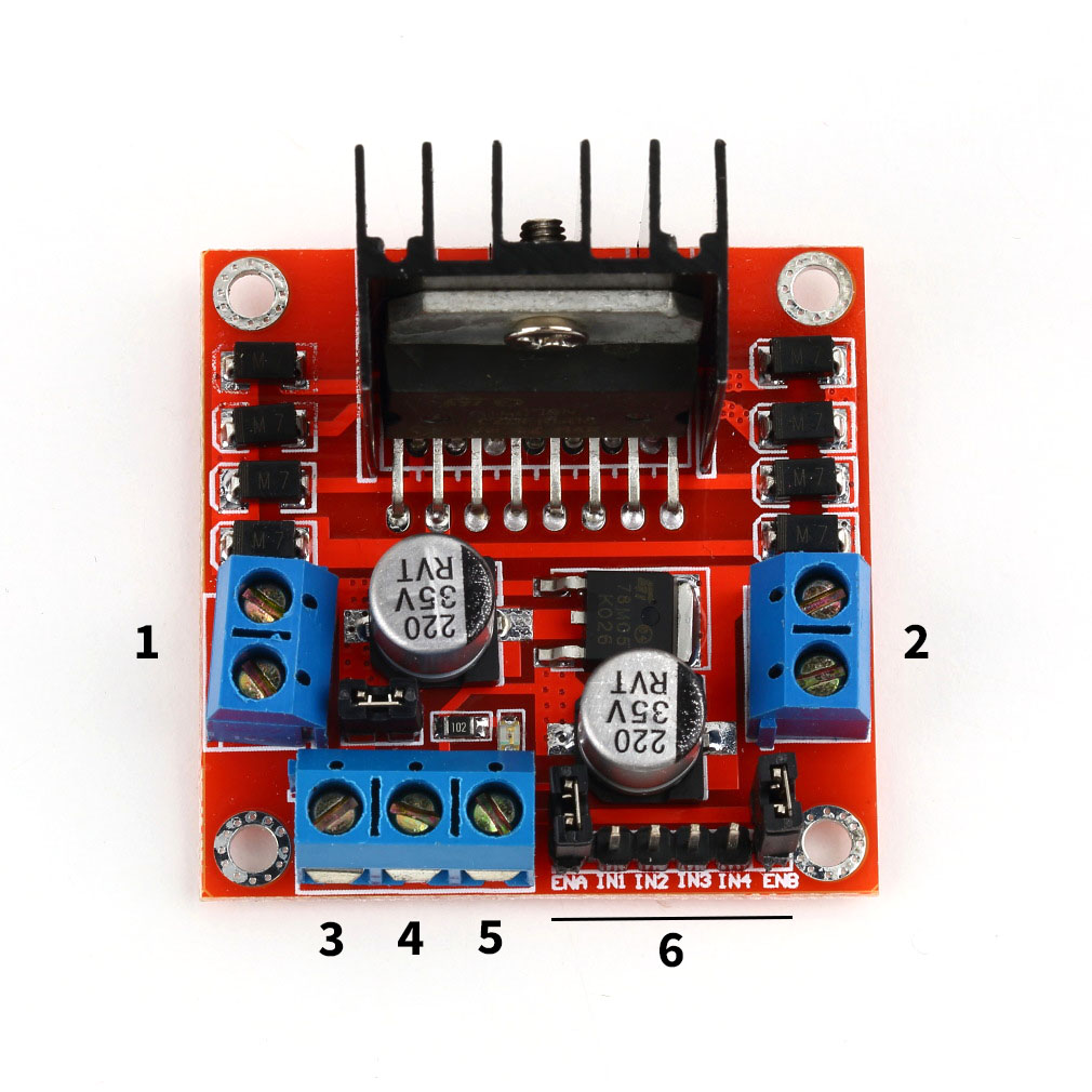
This module can drive two motors up to 2000mA each and maximum 50 volts. That’s perfectly fine as our motors will only be driven from the 4xAA batteries which is 6 volts in total. The two motors are connected to port 1 and port 2 (see numbers on the image). Wires can be interchanged as reversed polarity only makes the motors go in reverse.
Behind pin 3 and 4 there is a jumper. If this jumper is in place then you have to make sure your supply voltage is lower than 12V. It will also allow you to use pin 5 as regulated 5V output for your Arduino. On my car I connected the positive wire from the battery pack to pin 3 and the ground wire to number 4. Next I connected the 5V output pin from the motor drive module, which is pin number 5, to my Arduino Nano’s 5V pin and I also connected pin number 4 to my Arduino’s GND. Power is now connected.
The 6 pins marked with number 6 are there to take motor control commands from the Arduino, 3 for each motor. Here’s how it works:
-
ENA and ENB are the enable pins for the two motors. If the jumper is in place the motors will be driven at full speed. If we take off the jumpers and connect a PWM signal from the Arduino to them then we can change the speed of the motors.
-
IN1 and IN2 can change the direction of motor number 1. If we send HIGH to IN1 and LOW to IN2 then the motor will go forward, if IN1 is LOW and IN2 is HIGH then the motor will go backwards. The same applies to the second motor and the IN3 and IN4 pins.
-
If I want to run the first motor at half speed forward then ENA is a PWM value of 128, IN1 is HIGH and IN2 is LOW
-
If I want to run the second motor at full speed backwards then ENB is a PWM value of 255, IN3 is LOW and IN4 is HIGH
I added a 1000uF to pin 4 and 5 as the motors draw a lot of current when speeding up and the Arduino restarted quite often when there was a voltage drop. This fixed the problem and now the the motor drive circuit done.
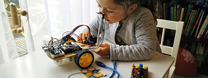
The hardware build was so easy that my 4-year-old daughter managed to understand the circuit and what each of the components do.
Autonomous mode and the ultrasonic sensor
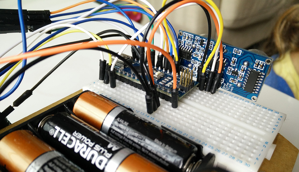
I used a cheap ultrasonic distance sensor with a 4 meter range. That’s perfectly enough as I set the obstacle detection limit to only 20 centimetres. The sensor has 4 pins: VCC is connected to the Arduino’s 5V pin, GND to GND, Trig to D6 and Echo to D5.
The example code to read the sensor is only a few lines:
#define trigPin 6
#define echoPin 5

void setup() {
  Serial.begin (9600);
  pinMode(trigPin, OUTPUT);
  pinMode(echoPin, INPUT);
}

void loop() {
  float duration, distance;
  digitalWrite(trigPin, LOW);
  delayMicroseconds(2);
  digitalWrite(trigPin, HIGH);
  delayMicroseconds(10);
  digitalWrite(trigPin, LOW);
  duration = pulseIn(echoPin, HIGH);
  distance = (duration / 2) / 29.1;

  if (distance >= 400 || distance <= 0){
    Serial.println("Out of range");
  }
  else {
    Serial.print(distance);
    Serial.println(" cm");
  }
}
After I had all the motors and the distance sensor connected up I put the motors into a continues forward motion for the autonomous mode. In the meantime the car was constantly checking the distance sensor and instructed the motors to steer away until there was no longer anything in front. Here's what I did in the loop() function:
// Get Distance sensor
  float duration, distance;
  digitalWrite(trigPin, LOW);
  delayMicroseconds(2);
  digitalWrite(trigPin, HIGH);
  delayMicroseconds(10); // Added this line
  digitalWrite(trigPin, LOW);
  duration = pulseIn(echoPin, HIGH);
  distance = (duration / 2) / 29.1;

  if(distance > 20) {
    digitalWrite(rightBackward, LOW);
    digitalWrite(rightForward, HIGH);
    digitalWrite(leftBackward, LOW);
    digitalWrite(leftForward, HIGH);
    analogWrite(enableRight, 200);
    analogWrite(enableLeft, 200);
  } else {
    digitalWrite(rightBackward, LOW);
    digitalWrite(rightForward, HIGH);
    digitalWrite(leftBackward, HIGH);
    digitalWrite(leftForward, LOW);
    analogWrite(enableRight, 200);
    analogWrite(enableLeft, 200);
    delay(100);
  }
Manual mode and the joystick shield
This was a little bit more complicated as we now have wireless communication. The controller was an Arduino UNO with a joystick shield. You can also see the nRF24l01 antenna on the left top corner.
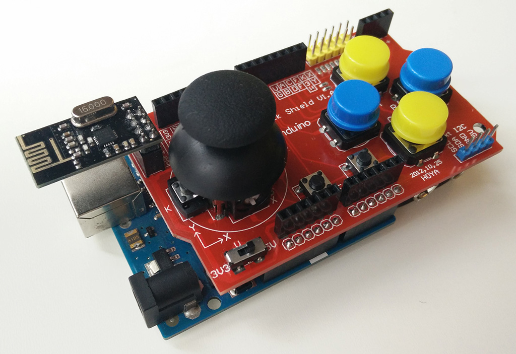
This controller was powered from a 9V battery. The button and the joystick on the shield are simple sensors so you can read them with the digitalRead() and analogRead() functions. The below piece of code is the final code I have for the joystick. It first checks the state of the joystick then sends through the wireless messages through the nRF24l01 module.
#include <SPI.h>
#include <RF24.h>
#include <RF24_config.h>

// Radio pin setup
#define cePin 9
#define csnPin 10

#define joyX A0
#define joyY A1

// Init RF24 radio
RF24 radio(cePin, csnPin);
const uint64_t pipe0 = 0xF0F0F0AA;
uint8_t p0 = 0;

// Variables
int chr[1];
int terminateChar[1];
String dataToSend = "";

void setup() {
  Serial.begin(9600);
  radio.begin();
  radio.openWritingPipe(pipe0);
}

void loop() {
    dataToSend += map(analogRead(joyX), 0, 1023, 0, 9);
    dataToSend += map(analogRead(joyY), 0, 1023, 0, 9);
    int stringSize = dataToSend.length();
    for (int i = 0; i < stringSize; i++) {
      int charToSend[1];
      charToSend[0] = dataToSend.charAt(i);
      radio.write(charToSend,1);
    }
    terminateChar[0] = 2;
    radio.write(terminateChar, 1);
    dataToSend = "";
}
To read this from the car you open a reading pipe then check the radio.available() function for incoming messages. Below is the final piece of code that is running on the car:
#include <SPI.h>
#include <RF24.h>
#include <RF24_config.h>

// Radio pin setup
#define cePin 9
#define csnPin 10

// US sensor pin setup
#define trigPin 14
#define echoPin 2
#define accuracy 4

// Motor pin setup
#define enableLeft 6
#define leftForward 4
#define leftBackward 3

#define enableRight 5
#define rightForward 8
#define rightBackward 7

// Init RF24 radio
RF24 radio(cePin, csnPin);
const uint64_t pipe0 = 0xF0F0F0AA;
uint8_t p0 = 0;

// Variables
String receivedMessage = "";
int chr[1];
int joyX = 4;
int joyY = 4;
int speedCoeff = 0;
int left = 0;
int right = 0;

void setup(){
  // Setup RF24 radio
  Serial.begin(9600);
  radio.begin();
  radio.openReadingPipe(p0, pipe0);
  radio.startListening();

  // Setup US sensor
  pinMode(trigPin, OUTPUT);
  pinMode(echoPin, INPUT);

  // Setup LEFT whel
  pinMode(enableLeft, OUTPUT);
  analogWrite(enableLeft, 255);

  pinMode(leftForward, OUTPUT);
  digitalWrite(leftForward, LOW);

  pinMode(leftBackward, OUTPUT);
  digitalWrite(leftBackward, LOW);

  // Setup RIGHT wheel
  pinMode(enableRight, OUTPUT);
  analogWrite(enableRight, 255);

  pinMode(rightForward, OUTPUT);
  digitalWrite(rightForward, LOW);

  pinMode(rightBackward, OUTPUT);
  digitalWrite(rightBackward, LOW);
}

void loop(){
  // Get Distance sensor
  float duration, distance;
  digitalWrite(trigPin, LOW);
  delayMicroseconds(2);
  digitalWrite(trigPin, HIGH);
  delayMicroseconds(10); // Added this line
  digitalWrite(trigPin, LOW);
  duration = pulseIn(echoPin, HIGH);
  distance = (duration / 2) / 29.1;

  // Watch control messages
  while(radio.available()){
    radio.read(chr, 1);
    char receivedChar = chr[0];

    if (chr[0] != 2){
      receivedMessage.concat(receivedChar);
    } else {
      joyX = receivedMessage.substring(0,1).toInt();
      joyY = receivedMessage.substring(1,2).toInt();

      if(distance < 15){
        joyX = 4;
        joyY = 4;
      }

      if(joyY < 4){
        // Backward
        digitalWrite(rightBackward, HIGH);
        digitalWrite(rightForward, LOW);
        digitalWrite(leftBackward, HIGH);
        digitalWrite(leftForward, LOW);
        speedCoeff = map(joyY, 0, 4, 255, 0);
        speedCoeff = speedCoeff < 0 ? 0 : speedCoeff;
        speedCoeff = speedCoeff > 255 ? 255 : speedCoeff;
      } else if(joyY > 4){
        // Forward
        digitalWrite(rightBackward, LOW);
        digitalWrite(rightForward, HIGH);
        digitalWrite(leftBackward, LOW);
        digitalWrite(leftForward, HIGH);
        speedCoeff = map(joyY, 4, 9, 0, 255);
        speedCoeff = speedCoeff < 0 ? 0 : speedCoeff;
        speedCoeff = speedCoeff > 255 ? 255 : speedCoeff;
      }

      right = map(joyX, 4, 9, 255, 0);
      right = right < 0 ? 0 : right;
      right = right > 255 ? 255 : right;

      right = (right + speedCoeff) / 2;
      analogWrite(enableRight, right);

      left = map(joyX, 0, 4, 0, 255);
      left = left < 0 ? 0 : left;
      left = left > 255 ? 255 : left;

      left = (left + speedCoeff) / 2;
      analogWrite(enableLeft, left);

      if(joyY == 4){
        // Stopped
        if(joyX < 4){
          // Left
          digitalWrite(rightBackward, LOW);
          digitalWrite(rightForward, HIGH);
          digitalWrite(leftBackward, HIGH);
          digitalWrite(leftForward, LOW);

          right = map(joyX, 0, 4, 255, 0);
          right = right < 0 ? 0 : right;
          right = right > 255 ? 255 : right;
          analogWrite(enableRight, right);

          left = map(joyX, 0, 4, 255, 0);
          left = left < 0 ? 0 : left;
          left = left > 255 ? 255 : left;
          analogWrite(enableLeft, left);

        } else if(joyX > 4){
          // Right
          digitalWrite(rightBackward, HIGH);
          digitalWrite(rightForward, LOW);
          digitalWrite(leftBackward, LOW);
          digitalWrite(leftForward, HIGH);

          right = map(joyX, 4, 9, 0, 255);
          right = right < 0 ? 0 : right;
          right = right > 255 ? 255 : right;
          analogWrite(enableRight, right);

          left = map(joyX, 4, 9, 0, 255);
          left = left < 0 ? 0 : left;
          left = left > 255 ? 255 : left;
          analogWrite(enableLeft, left);

        } else if (joyX == 4){
          // Stopped
          digitalWrite(rightBackward, LOW);
          digitalWrite(rightForward, LOW);
          digitalWrite(leftBackward, LOW);
          digitalWrite(leftForward, LOW);
          analogWrite(enableRight, 0);
          analogWrite(enableLeft, 0);
        }
      }
      receivedMessage = "";
    }
  }
}
I also got the bluetooth communication working between my phone and the Arduino but only with an Arduino UNO. It’s probably because the Arduino Nano I was using in this project requires a 3.3V signal level on RX and TX and the UNO can take 5V. If you have done this before please email me and let me know!