Powering your Arduino projects could be a tricky task especially if you want to run it from a battery or from 230 V AC. Luckily, there are many ways to alter the voltage in a circuit to match the required amount for the Arduino.
Learn more about the Web on Devices Solar Energy Shield which is a great tool for power management in Arduino projects.
The recommended input voltage for your Arduino UNO is 7 - 12 V when connected to the USB port or the barrel plug. This can be a limitation if you want to power it from a very common 3.7 V lithium-polymer battery, plug it into a 230 V wall socket, or maybe use 3 AA batteries in a battery pack (which would give you only 4.5 V). And there are other development boards like the ESP8266 Wi-Fi module which operates at 3.3 V.
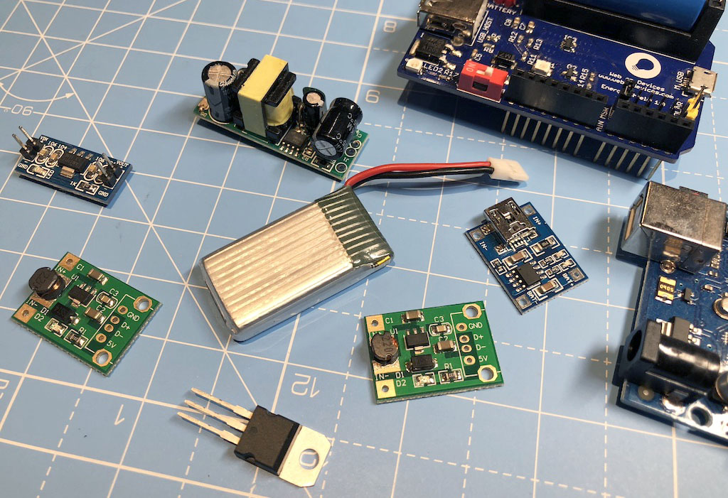
In this post we are going to discover a few different ways to adjust the voltage and supply power to your Arduino projects.
Boost
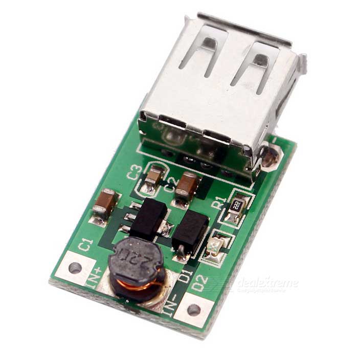
Voltage boost circuits are required in case you wish to increase the voltage from what was originally supplied. This cheap boost circuit module pictured below can take any DC input voltage between 1 - 5 V and output regulated 5 V.
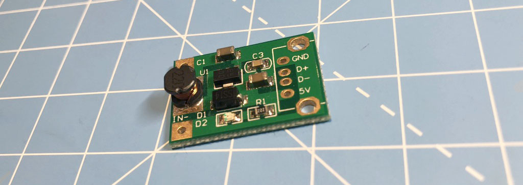
This is perfect in situations where you want to power your 5 V Arduino from:
- a 3.7 V li-po battery
- a 3.6 V lithium battery
- one, two or three 1.5 V AA or AAA battery in a battery pack (this would give 1.5 V, 3 V or 4.5 V)
- any other battery outputting in the 1-5 V range
These boost modules are available with a USB port on the output side. With this you could very easily build a mobile phone charger using AA or AAA batteries. This is because phone chargers and regular USB ports also supply 5 V.
Once the input power is connected to the module from any of the sources listed above, you can plug in a regular USB cable to power the Arduino.
AC-DC converter
This is essentially what you have in all phone chargers or laptop chargers. They can convert 230 V AC power from your wall socket to a much lower DC voltage. The output voltage is most often 12 V, 9 V, 6 V or 5 V.
This small module can convert voltages from 90 V - 240 V to 5 V:
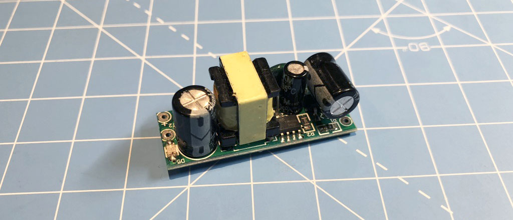
You can use this to power your Arduino project from a mains outlet, however, since you need to work with bare wires here, it's not the recommended way, especially for beginners. You can very easily cross the wires on the AC side and short circuit 230 V which can be quite dangerous.
Be careful when working with 230 V and bare wires. High voltage can kill so only work with this module if you’re an experienced or qualified electrician.
Instead, you are probably better off using an off-the-shelf wall adapter or phone charger and work with the wires at the DC side which has already been safely regulated to a much lower voltage.
The only issue with most of these adapters is that their connector is very rarely the correct size for the famale barrel plug on the UNO and almost never a USB type-b connector which is what the Arduino UNO requires.
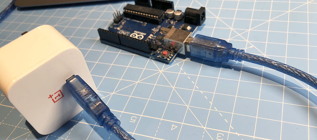
An exception to this are the phone chargers with USB ports and replaceable cables:
For situations where you are working with an incompatible adapter, I'd recommend buying a couple of male barrel plug adapters with screw terminals. With this you can connect the cleaned wires from a 9 or 12 V AC-DC adapter to the screw terminals and safely connect power to the Arduino input plug. Just make sure you buy a standard 2.1 mm centre positive barrel jack connector.
Voltage regulator
In case your input voltage is not as high as 230 V and not AC but you still need 5 V output then you can just use a simple 5 V voltage regulator. This chunky regulator will help you get your 7-35 V DC input to a nice clean 5 V.
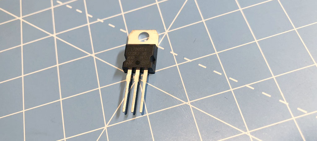
I used one of these in my 12 V RGB LED light project where I powered the LED ribbon from a 12 V AC-DC mains adapter then used a 5 V voltage regulator to power the Particle Photon dev board from the same adapter. This way I didn’t have to introduce another 230 V AC-DC converter with a different output just used the already regulated 12 V input and regulated that further down to 5 V.
Here you can find more details about this project.
Voltage regulators are cheap and very easy to work with, but keep in mind that they are not very efficient, compared to transformers like the AC-DC adapters we have already mentioned, as they dissipate the regulated voltage in the form of heat.
Step-down
Next up, we have a tiny module that takes inputs between 4.5 V and 7 V and outputs regulated 3.3 V for your ESP8266 or other dev boards.
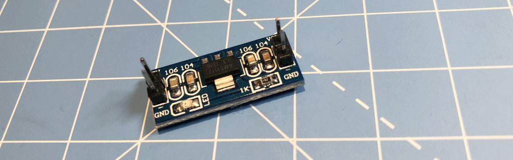
This works with 5 V USB power, three or four AA or AAA batteries, or if you have a 5 V or 6 V wall adapter.
This step-down component is essentially just a voltage regulator in a nicer module form.
Voltage divider circuit
Finally, let’s mention the voltage divider circuit which is the simplest of all. A voltage divider is a very simple circuit to turn a large voltage into a smaller one. Using just two series resistors and an input voltage, we can create an output voltage that is a fraction of the input.
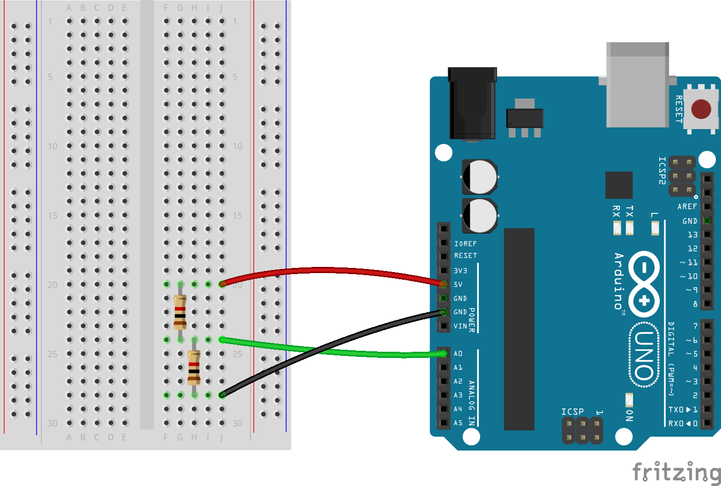
The output voltage will be determined by the ratio of the two resistor which can be calculated with this equation:
Vout = Vin * (R2 / (R1 + R2))It’s easy to see that if we simply add two resistors with the same resistance the output voltage will be halved:
Vout = 5V * (1000 / (1000 + 1000))
Vout = 5V * 0.5
Vout = 2.5V
You can control the output voltage by changing the resistance of one of the resistors. There’s also nothing preventing you from changing one of the resistors to a potentiometer or a light dependent resistor as these are just special types of resistors that can change their resistance value depending on user input or environmental light changes.
This is one of the most basic circuits in electronics so it's important to discuss if it can or can't be used to supply power to a load.
The short answer is NO: a voltage divider circuit can't be used as a power supply.
Voltage divider circuits are often used in sensors where only a small amount of current is passing.
If this circuit was used as a power supply, the current required by the load would have to pass through one of the resistors which produces power that is dissipated in the form of heat. If the power is higher than the rating of the resistor (usually maximum 1 W) the heat could potentially melt the component.
Heat and melting is just one of the problems, the inefficient nature of this circuit is another: dissipating power in the form of heat is a waste of energy.
You can read more about the light dependent resistor and measuring light in my free Ebook that you can download right below this post.
Power Shield
The super easy option to power your Arduino project is to use a power shield. Web on Devices has developed its own power shield with an on-board lithium-ion battery and a solar panel to recharge itself.
Learn more about the Web on Devices Energy Shield in this post.