Last time we built an Arduino robot car with an ultrasonic distance sensor and added some logic to automatically steer away from obstacles. It could also be manually driven with a second Arduino from the joystick shield added to it. The two were communicating via NRF24 radio modules.
Today we extend this robot car with a line-follow sensor and add some new application logic. With this it will automatically drive along a black line (or a white line if you set it up differently).
If you are getting started from scratch, just go back to the previous post and follow the build instructions there. Please note that the pins will be connected to different outputs in this example, but everything remains the same.
The final source code for the project can be found on Github: https://github.com/webondevices/example-projects/tree/master/car-line-follow
And here's the source code for the obstacle avoiding logic: https://github.com/webondevices/example-projects/tree/master/car-obstacle-avoid
Line follow sensor
This simple analog sensor has three infrared LEDs facing downwards that can detect contrast differences in light. As a result, it will output 5 V and the code will report HIGH when one of the sensors detect black and 0 V and LOW when there's only a white sheet of paper under the sensor.
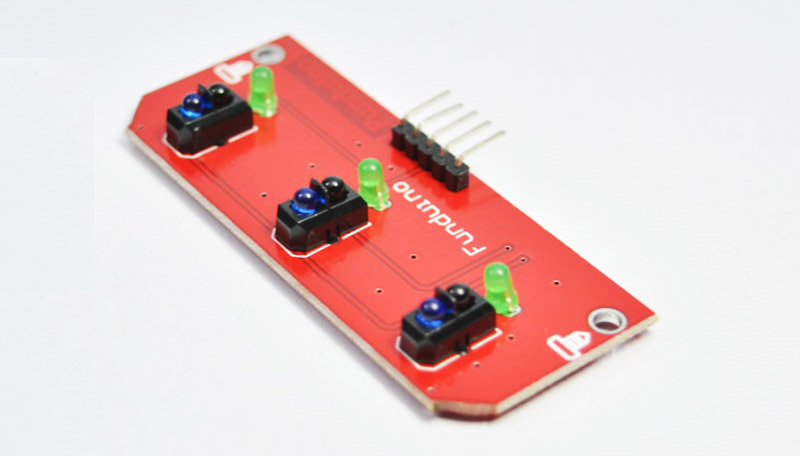
This sensor module has three infrared LEDs and three output pins, so you will need to interpret the position of the black line by evaluating the values reported by all three infrared sensors at the same time.
Here are some of the possible scenarios:
- all three sensors report LOW: only white background is visible
- LOW, HIGH, LOW: the black line is in the middle, under the centre inrared sensor
- HIGH, LOW, LOW: the black line is under the left infrared sensor
- LOW, LOW, HIGH: the black line is under the right infrared sensor
Setting this sensor up in the Arduino code is very simple as the module exposes three digital output pins for the three infrared LED sensors. You simply connect these to 3 digital pins. I randomly picked D4, D3 and D2.
The Arduino sketch to read and interpret the measurements is only a couple of lines of code:
int lft = 4;
int ctr = 3;
int rgt = 2;

void setup() {
    // Set all line follow pins as input
    pinMode(lft, INPUT);
    pinMode(ctr, INPUT);
    pinMode(rgt, INPUT);
}

void loop() {
    int left = digitalRead(lft);
    int centre = digitalRead(ctr);
    int right = digitalRead(rgt);

    // 001
    if (left == 0 && centre == 0 && right == 1) {
        // Line under right sensor
    }

    // 100
    if (left == 1 && centre == 0 && right == 0) {
        // Line under left sensor
    }

    // 000 or 010
    if ((left == 0 && centre == 0 && right == 0) || (left == 0 && centre == 0 && right == 0)) {
        // Line under middle sensor or invisible
    }
}
This is the most basic logic possible to work with the incoming signals. In the final version of the code we also have some logic to handle situations where the line is thicker than usual and it might be detected by two sensors at the same time.
Steering
The obstacle avoiding robot sketch had some higher level functions defined to help turning the car into direction: moveForward(), turnLeft(), turnRight();
We can call these depending on the different line positions:
- If line is on the left side: turn right!
- If line is on the right side: turn left!
- If line is in the centre: go straight on!
In the final version of the Arduino sketch, witch also takes some the edge cases into consideration, the motor drive functions are also called to take action:
int left = digitalRead(lft);
int centre = digitalRead(ctr);
int right = digitalRead(rgt);

// 010
if (left == 0 && centre == 1 && right == 0) {
    moveForward(100);
}

// 011 || 001
if ((left == 0 && centre == 1 && right == 1) || (left == 0 && centre == 0 && right == 1)) {
    turnRight(100);
}

// 110 || 100
if ((left == 1 && centre == 1 && right == 0) || (left == 1 && centre == 0 && right == 0)) {
    turnLeft(100);
}

// 000
if (left == 0 && centre == 0 && right == 0) {
    moveForward(0);
}
Notice how in the "000" scenario the moveForward function is called with 0 passed in to move the motors forward with the speed of 0, which essentially means: stop the car.
The complete code combined with the previously discussed motor drive logic can be found here on Github: https://github.com/webondevices/example-projects/tree/master/car-line-follow
Future improvements
Some complain that with this very basic logic the car goes along with a jittery back and forth steering movement. This happens even when the car is expected to go along a perfectly straight line.
To improve this issue you could invest into a line follow sensor that has 5 ore more sensors. with this you could change the angle of steering depending on how far out the line is from the center.
However, the best way to improve the application logic would be to make the car work with angles and curves. This would mean the car would start turning into a curve when the line is off center and it would increase the angle of the curve until the line is back in the middle. With this improved logic the car would carry on going along a curve after the line is back in the middle.
If you manage to improve the steering logic, I will publish your solution on Web on Devices!